
As we prepare to launch the PropBoard and release version 1.0.2 soon, I post here what BETA testers would have to do to keep using their BETA boards.
As soon as you download the 1.0.2 version of the software (or any version after 1.0.1) you have to modify the c:\users\%username%\AppData\Local\Arduino15\packages\artekit\hardware\stm32f4\1.0.2\boards.txt file. Add the -DBETA_BOARD define to the end of the propboard.build.extra_flags property. Like this:
propboard.build.extra_flags=-DSTM32F401xx -DHSE_VALUE=10000000 -mthumb -DUSE_STDPERIPH_DRIVER -DARM_MATH_CM4 -DBETA_BOARD
That’s the only way I’ve found to not add an extra board to the package.
Mute pin: If for any reason you were muting the amplifier directly using the PB14 pin, note that in the v1.7 version of the board the pin has been moved to PA15. You can still address this pin with the digitalWrite function using the AUDIO_MUTE define.
Since the documentation will change, here follows the instructions to change the power supply range.
Changing the power supply range
The PropBoard is optimized to work with a 5.5V to 12V power supply range, but you can change this range by making some modifications to the board. This is very useful if you want to use WS2812B LED strips (see the LedStrip library).
The downside of the 3.7V to 5V range is that you will lose some audio output volume, and on some LEDs brands and/or colors (specially blue and green ones) there may be a brightness loss. In this case you may be able to compensate by incrementing the PWM duty cycle by setting a higher maximum forward current to the HBLED::begin function. To do this change in the code you have to be able to measure the LED power consumption with a multimeter on the LED output.
Remember that an excessive output current setting may damage your LEDs.
5.5V to 12V power supply range
Here follows a picture of a board set to operate in the 5.5V to 12V power supply range:
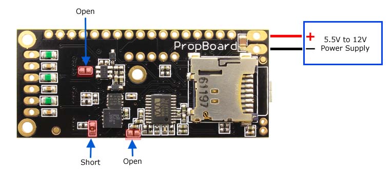
In the picture up here, the component pointed by “short” is a 0 Ohm resistor (R13 in the schematics). If you have removed it already, short the pads with some solder. The other two pads (J7 and J10 in the schematics) are solder jumpers, that have to be open.
3.7V to 5V power supply range
If you want to use the 3.7V to 5V power supply range, make the following modifications:
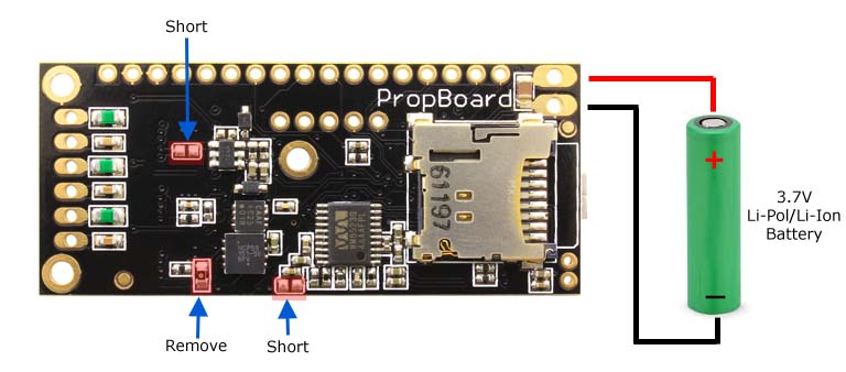
Short the pads marked as “short” (J7 and J10 in the schematics) with solder and remove the R0 resistor (R13 in the schematics).
When the board is configured to operate in 3.7V to 5V power supply range, applying a higher voltage than 5V can permanently damage the board. And of course, modifications to the board must be done with the batteries disconnected
