Complete wiring schedule + programming

Hi All,
After making a simple lightsaber with light only, I wanted to make a more impressive one.
I purchased the ProBboard (now on it way to me) and started to read the options from the PBSaber firmware, PropBoard manual and INI files.
I’m a technician with no experience in programming, but I do understand the steps. I still have have some questions after reading the manual. It gives me a good guidance of different steps, but not a clear total image.

First of all the wiring:
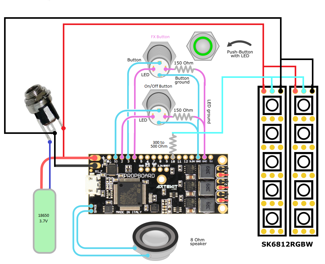
I want to use SK6812RGBW Led strips (2x 1m 144leds), Pushbuttons with led ring, 18650 Battery (1 or 2), 8 Ohm speaker and a DC charging port.
For this I made the following total picture:

Can you let me know if the wiring is correct?

  1. Need of 150 Ohm resistor on the Buttons to ground. Is this correct?
  2. Must there be a resistor on the data wire from the Lede strips? If so what size?
  3. Battery: 3,7 V or 7,4 V? Can’t figure out when to use which voltage.
  4. Must there be a resistor in the + line of the Led strip when using 7,4V? (120 Ohm??)
  5. The leds in the pushbuttons are rated 12V. Must there be a resistor in GRD line?

Now the programming (sorry for my low skills in this):
The firmware upload is clear and the INI file is also clear.
As you can see on the schematic I want to use 2 push buttons with Led ring.
I’ve seen the Propbutton Library, but where do you use this on the PBSaber firmware?
Can you give me any guidance here please?

Thanks in advance for your feedback

Hello @Jurgen,

The design seems OK, except for the things I answer here below. You can avoid the GND connection going from the LED strip to the GND pad of the PropBoard (the thin black line).

You need it on any LED pin of the button. It can be either positive or ground. The resistor is one for each LED so you will need two resistors.

From the PBSaber manual:

It is advised to put a 300 to 500 Ohms resistor between the data line and the PropBoard pad. This is to avoid damaging the microcontroller pin or the first LED in the LED strip in the case the data line is connected before VCC and ground.

For LED strips like the SK6812RGBW you have to use a single battery. Otherwise you will be sending 7.4V to the LED strip and you can damage it. So for this setup, single battery = 3.7V. You can find instructions on how to change it here.

Answers for questions 4 and 5 are related to the answers I wrote up here. If something is not still clear, please let me know.

Regarding programming, if at the moment of purchase you chose the PBSaber firmware option, then you don’t need to do any coding (unless you want to); just modifying the config file for your LED strip, colors, fonts, etc.

Note about buttons with LEDs: at the moment, the PBSaber firmware doesn’t drive the button’s LEDs, so they will be off all the time. You can connect them though, and we can figure out some modifications to the code to make them blink accordingly once you get your setup going.

Hi Ivan,
Thanks for you reply.
I modified the schematics and it should be as you described now:

Ok will do so. I will contact you when the setup is complete.

1 Like